This simple Arduino project can limit the number of people inside a shop and maintain social distancing in an automated contact free way.
COMPONENTS AND SUPPLIES
_ztBMuBhMHo.jpg?auto=compress%2Cformat&w=140&h=140&fit=fill&bg=ffffff) |
| × | 1 | |||
 |
| × | 2 | |||
 |
| × | 1 | |||
 |
| × | 1 | |||
 |
|
Step 1: Assembling the Circuit
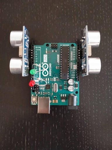
Please refer to the above images for assembly and also the bullet points below.
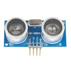
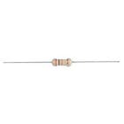
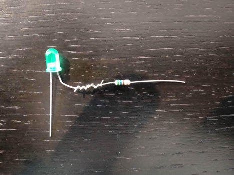
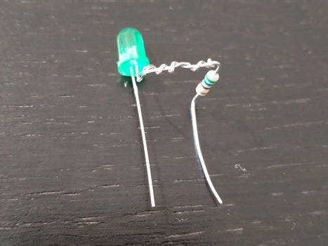
To attach the LED anode (positive leg) and resistor together I have used a technique called the Western Union (or Lineman) splice. This creates a mechanically strong electrical connection between the wires without solder. Be careful not to injure yourself on the sharp ends of the wires - using a pair of pliers and safety glasses is safest. If you prefer, you can connect the LED anode to a resistor leg with a female to female jump wire. Some HC-SR04 sensors come with straight pins, these should be attached to the Arduino with female to male jumper wires.
The components should then be attached as follows:
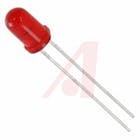
- The red LED cathode goes to GND
- The red LED's resistor (spliced to the anode) goes to pin 12
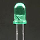
- The green LED cathode goes to pin 11 (this will be set to GND later)
- The green LED's resistor (spliced to the anode) goes to pin 9
- The first HC-SR04 connects: Vcc to pin A0, TRIG to A1, ECHO to A2, and GND to A3
- The second HC-SR04 connects: Vcc to pin 2, TRIG to 3, ECHO to 4, and GND to 5
That's it; no soldering!
Step 2: Writing and Uploading the CodeThe counter must calibrate to its surroundings in the setup() function, then detect and count people in the loop() function.
The calibration takes five readings form each sensor and averages them - this is the distance to the nearest wall. The threshold for detecting someone is then set as 75% of this value - this avoids the sensor being triggered or becoming uncalibrated if the product is knocked slightly. If the calibration returns silly values, like 0 cm or 300 cm, then the default threshold of 45 cm is used. Both LEDs are lit during this calibration phase to alert the user that it is ongoing. The product can be recalibrated at any time by pressing reset on the Arduino, this also resets the count to zero.
The loop takes a reading from each sensor. If this reading is less than the threshold then there is someone in that channel. If the previous reading from this sensor implied that no-one was there then the count increases for the in-sensor or decreases for the out-sensor. Comparing to the previous state of the sensor allows us to catch the rising-edgeof the signal. The last thing to do is check the count against limit, if count >= limit light the red LED, else light the green LED.


Comments
Post a Comment